As I mentioned in a recent post, I’m going to implement the solutions for this section in PLT Scheme rather than in Common Lisp. This is because of the very easy access to a GUI library in PLT Scheme, which is a difficult task with CL if you’re on Windows.
The picture I’m going to use for these sections is just some funny collection of lines I’ve built named “krest” (I’ll show the code that creates it later):
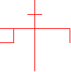
Also, note that the solutions to the first exercises “assume” the existence of code written for later exercises. Ultimately, all the code for the picture language is here, it is just arranged in the order of the exercises it solves.
There’s a very important point the authors are making in the beginning of the section that is worth mentioning:
Once we can combine painters, we would like to be able to abstract typical patterns of combining painters. We will implement the painter operations as Scheme procedures. This means that we don’t need a special abstraction mechanism in the picture language: Since the means of combination are ordinary Scheme procedures, we automatically have the capability to do anything with painter operations that we can do with procedures.
DSLs (Domain Specific Languages) are hot stuff lately. But they’ve always been used by serious programmers (SICP was written more than 20 years ago…), and their theoretical base is very solid. DSLs can be external (like the language of Makefiles) and internal (like Ruby-on-Rails). Internal DSLs are built on top of an existing programming language, and can therefore use all its facilities. This is exactly what the authors mean in the quote above. The picture language is an internal DSL, built on top of Scheme.
Exercise 2.44
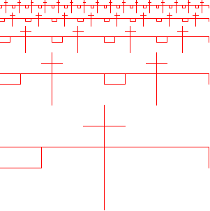
Here is the definition of up-split (again, note this is Scheme code, not Common Lisp):
(define (up-split painter n)
  (if (zero? n)
    painter
    (let ((smaller (up-split painter (- n 1))))
      (below painter (beside smaller smaller)))))
And this is what it produces, applied to krest 4 times:
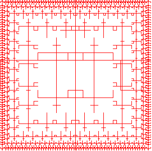
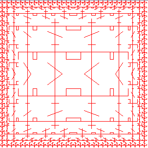
And square-limit produces:
Exercise 2.45
The key here is to look carefully at right-split and up-split and see what’s similar between them. It is immediately obvious that the two functions are very much alike, and the only difference between them is the order of calls to blow and beside on the last line. So we can define the generic split as follows:
(define (split combine-main combine-smaller)
  (lambda (painter n)
    (if (zero? n)
      painter
      (let ((smaller ((split combine-main combine-smaller) painter (- n 1))))
        (combine-main
          painter
          (combine-smaller smaller smaller))))))
Exercise 2.46
(define (make-vect x y)
  (cons x y))

(define (xcor-vect v)
  (car v))

(define (ycor-vect v)
  (cdr v))

(define (add-vect v1 v2)
  (make-vect
    (+ (xcor-vect v1) (xcor-vect v2))
    (+ (ycor-vect v1) (ycor-vect v2))))

(define (sub-vect v1 v2)
  (make-vect
    (- (xcor-vect v1) (xcor-vect v2))
    (- (ycor-vect v1) (ycor-vect v2))))

(define (scale-vect s v)
  (make-vect
    (* s (xcor-vect v))
    (* s (ycor-vect v))))
Exercise 2.47
Here is the implementation for the list representation:
(define (make-frame dc origin edge1 edge2)
  (list dc origin edge1 edge2))

(define (dc-frame f)
  (car f))

(define (origin-frame f)
  (cadr f))

(define (edge1-frame f)
  (caddr f))

(define (edge2-frame f)
  (cadddr f))
Whoa, stop right there ! What is that dc thingy ? dc is a shortname for “device context”, which is an object commonly used in GUIs for an area you can draw on. As I mentioned, I use the PLT Scheme implementation for this section, with its GUI library MrEd (based on wxWindows).
This is how I create new frames for drawing:
(define (make-fr1)
  (make-frame
    dc
    (make-vect 0 0)
    (make-vect 300 0)
    (make-vect 0 300)))
Here is the infrastructure drawing code:
(define frame
  (instantiate
    frame%
    ("Drawing Example")
    (width 700)
    (height 700)))

;; Make the drawing area
(define canvas (instantiate canvas% (frame)))
;; Get the canvas's drawing context
(define dc (send canvas get-dc))

(define red-pen (instantiate pen% ("RED" 1 'solid)))

;; Show the frame
(send frame show #t)
;; Wait a second to let the window get ready
(sleep/yield 1)

(my-draw)
As you can see, dc is a global variable – the device context of the canvas on which I draw. The drawing code itself is in the function my-draw. Here’s a sample my-draw:
(define (my-draw)
  (send dc set-pen red-pen)
  ((right-split krest-painter 4) (make-fr1))
)
What is krest-painter, though ?
(define (segments->painter segment-list)
  (lambda (frame)
    (for-each
      (lambda (segment)
        (draw-line
          (dc-frame frame)
          ((frame-coord-map frame) (start-segment segment))
          ((frame-coord-map frame) (end-segment segment))))
      segment-list)))

(define (draw-segment dc seg)
  (let ((v-start (start-segment seg))
        (v-end (end-segment seg)))
    (send dc draw-line
      (xcor-vect v-start)
      (ycor-vect v-start)
      (xcor-vect v-end)
      (ycor-vect v-end))))

(define (draw-line dc v1 v2)
  (draw-segment dc (make-segment v1 v2)))

(define krest-segments
  (list
    (make-segment
      (make-vect 0.4 0.2)
      (make-vect 0.6 0.2))
    (make-segment
      (make-vect 0.5 0.0)
      (make-vect 0.5 1.0))
    (make-segment
      (make-vect 0.0 0.4)
      (make-vect 1.0 0.4))
    (make-segment
      (make-vect 0.2 0.4)
      (make-vect 0.2 0.6))
    (make-segment
      (make-vect 1.0 0.4)
      (make-vect 1.0 0.6))
    (make-segment
      (make-vect 0.0 0.6)
      (make-vect 0.2 0.6))))

(define krest-painter (segments->painter krest-segments))
The rest of the code (segments, etc.) will be shown below. I know this is a lot of code and can be a little confusing, but all there is to it is the code presented by the authors, plus solutions to exercises, plus a little code for drawing with the MrEd GUI framework (which I don’t intend to teach here).
Hmm… that was quite a detour. Let’s get back to exercise 2.47 now.
The other representation uses cons:
(define (make-frame dc origin edge1 edge2)
  (cons dc (cons origin (cons edge1 edge2))))

(define (dc-frame f)
  (car f))

(define (origin-frame f)
  (cadr f))

(define (edge1-frame f)
  (caddr f))

(define (edge2-frame f)
  (cdddr f))
The only difference is in edge2-frame. While it wastes another cons cell, the list representation is much more comfortable and all the sequence functions work on it, so I find it preferable.
Exercise 2.48
(define (make-segment v-start v-end)
  (cons v-start v-end))

(define (start-segment seg)
  (car seg))

(define (end-segment seg)
  (cdr seg))
Exercise 2.49
(define outline-segments
  (list
    (make-segment
      (make-vect 0.0 0.0)
      (make-vect 0.0 1.0))
    (make-segment
      (make-vect 0.0 0.0)
      (make-vect 1.0 0.0))
    (make-segment
      (make-vect 1.0 0.0)
      (make-vect 1.0 1.0))
    (make-segment
      (make-vect 0.0 1.0)
      (make-vect 1.0 1.0))))

(define outline-painter (segments->painter outline-segments))

(define x-segments
  (list
    (make-segment
      (make-vect 1.0 0.0)
      (make-vect 0.0 1.0))
    (make-segment
      (make-vect 0.0 0.0)
      (make-vect 1.0 1.0))))

(define x-painter (segments->painter x-segments))

(define diamond-segments
  (list
    (make-segment
      (make-vect 0.5 0.0)
      (make-vect 1.0 0.5))
    (make-segment
      (make-vect 1.0 0.5)
      (make-vect 0.5 1.0))
    (make-segment
      (make-vect 0.0 0.5)
      (make-vect 0.5 0.0))
    (make-segment
      (make-vect 0.0 0.5)
      (make-vect 0.5 1.0))))

(define diamond-painter (segments->painter diamond-segments))
I won’t do the wave painter. Too much work (17 segments!) that won’t get me much farther in grasping the wisdoms of SICP, as this is only a drawing exercise.
Exercise 2.50
I’m not sure the authors have got rotate90 right. It appears to me it rotates the painter 90 degrees clockwise, rather than counterclockwise.
Here’s my set of counterclockwise rotations:
(define (rotate90 painter)
  (transform-painter
    painter
    (make-vect 0.0 1.0)     ; new origin
    (make-vect 0.0 0.0)     ; new end of edge1
    (make-vect 1.0 1.0)))   ; new end of edge2

(define (rotate180 painter)
  (transform-painter
    painter
    (make-vect 1.0 1.0)
    (make-vect 0.0 1.0)
    (make-vect 1.0 0.0)))

(define (rotate270 painter)
  (transform-painter
    painter
    (make-vect 1.0 0.0)
    (make-vect 1.0 1.0)
    (make-vect 0.0 0.0)))
To prove my point, here is the image of krest-painter rotated counterclockwise 0, 90, 180 and 270 degrees using my functions:
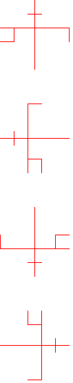
Looks correct, doesn’t it ? But my rotate90 is different from the one in the book! Is this the first bug I find in SICP, or have I misunderstood something ?!
Anyway, to complete the exercise, here’s flip-horiz:
(define (flip-horiz painter)
  (transform-painter
    painter
    (make-vect 1.0 0.0)
    (make-vect 0.0 0.0)
    (make-vect 1.0 1.0)))
Exercise 2.51
This is the straightforward implementation of below:
(define (below painter1 painter2)
  (let* ( (split-point (make-vect 0.0 0.5))
          (paint-up
            (transform-painter
              painter2
              (make-vect 0.0 0.0)
              (make-vect 1.0 0.0)
              split-point))
          (paint-down
            (transform-painter
              painter1
              split-point
              (make-vect 1.0 0.5)
              (make-vect 0.0 1.0))))
    (lambda (frame)
      (paint-up frame)
      (paint-down frame))))
And this is below using rotations and beside:
(define (below-rot painter1 painter2)
  (rotate90 (beside
              (rotate270 painter1)
              (rotate270 painter2))))
Exercise 2.52
I added a horizontal line to krest-painter and changed the way corner-split works (as suggested in b.):
(define (corner-split painter n)
  (if (zero? n)
    painter
    (let* ( (up (up-split painter (- n 1)))
            (right (right-split painter (- n 1)))
            (top-left up)
            (bottom-right right)
            (corner (corner-split painter (- n 1))))
      (beside (below painter top-left)
              (below bottom-right corner)))))

(define krest-segments
  (list
    (make-segment
      (make-vect 0.4 0.2)
      (make-vect 0.6 0.2))
    (make-segment
      (make-vect 0.5 0.0)
      (make-vect 0.5 1.0))
    (make-segment
      (make-vect 0.3 1.0)
      (make-vect 0.7 0.7))
    (make-segment
      (make-vect 0.0 0.4)
      (make-vect 1.0 0.4))
    (make-segment
      (make-vect 0.2 0.4)
      (make-vect 0.2 0.6))
    (make-segment
      (make-vect 1.0 0.4)
      (make-vect 1.0 0.6))
    (make-segment
      (make-vect 0.0 0.6)
      (make-vect 0.2 0.6))))
Here’s the result:
The options for playability are limitless, of course.
To conclude this fascinating section, I want to mention something one of the authors said in the video lecture on this topic. The picture language is a whole new way to describe pictures, and indeed for the specific need it was created it’s very convenient and flexible. Moreover, it really blurs the distinction between functions and data, because the main object is the painter, which is a function. It is an excellent exercise in abstraction and in higher order procedures.
Another small note: I think this language looks much better in Scheme than in Common Lisp, mainly because funcall is not needed. In any higher-order-procedure-heavy language, Scheme will look much cleaner.